
Acoustic Emission
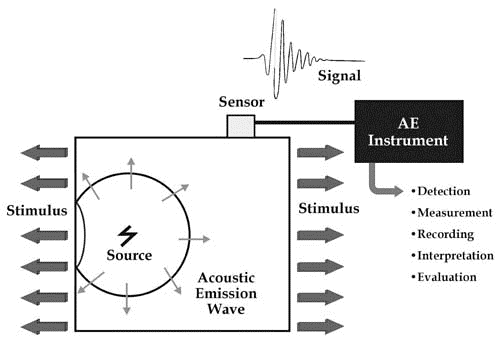
The acoustic emission (AE) technique utilises the detection of high frequency transient elastic waves emanating from a source within a structure which are converted to electrical signals by a surface mounted sensor for subsequent analysis . The source is the material itself and may be the result of localised yielding or cracking of the base material, or of the products resulting from corrosion. AE sensors are also used for leak detection on pressurised systems, signals from leakage are continuous in nature making this is a straightforward application.
Basis Of Acoustic Emission Testing
The piezoelectric sensor is mounted directly onto the surface of the structure, or, in the case of high temperature structures, on the end of a metal “waveguide” which is attached to the structure, usually by welding. For detection the source must be active during the monitoring period, which
means the structure needs to be stressed or operating. In the case of a shortterm test, additional stress is usually applied to the structure to stimulate activity. For pressure vessels this is typically hydrostatic or pneumatic. Where the damage of interest cannot be further stimulated by applying additional stress it may be necessary to monitor for an extended period, or even continuously. Monitoring during start-up or cool-down where major thermal stress occurs may be more appropriate for thick-wall high temperature plant.
The signal from the sensors is amplified using a low noise preamplifier, which also filters the signal and provides a line drive for long cables, in most instances the pre-amplification, filtering, line-drive, and a self-test pulse function is inside the sensor itself. The signal is further processed and then digitised by the AE system which extracts signal “features” and has software for identification and removal of extraneous noise, and graphing of the results. Relevant parameters such as pressure and strain are also measured and recorded by the AE system for correlation with the AE activity. AE systems are usually based around specialist PCI boards with digital signal processing, installed in an industrial PC or specialist chassis running PC software. The AE method, which is effectively seismology on a small scale, also locates the source of any emissions that reach multiple sensors by measuring the relative time arrival and carrying out “triangulation”. Location may be linear, two, or three dimensional, depending upon the sensor configuration. Advanced analysis methods used on the raw waveform are sometimes used to learn more about the source and its transmission path, on plated structures it is possible for example to establish the distance to source from a single waveform by analysis of the wave modes.
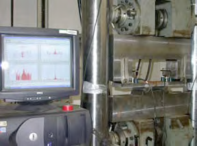
AET Data Acquisition in Progress
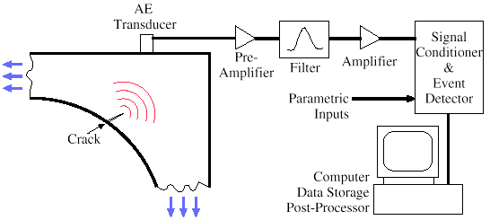
Schematic illustration of Acoustic Emission Testing Equipment
General inspection capabilities
The acoustic emission technique can be used to monitor defects which are active under the test conditions.
• Monitoring can take place from a number of locations whilst the plant is still in operation.
• Can detect faults or leakages in pressure vessels, tanks, and piping systems.
• AE is a non-invasive technique.
• Minimal disturbance to vessel or pipe insulation.
• Gives an immediate indication of the response and behaviour of the material under stress pertaining to factors such as strength, damage and
failure.
• Can be used for online monitoring of welding, corrosion and plant integrity on a permanent basis.
• Studies have shown that AE is capable of detecting and distinguishing between different stages of corrosion in atmospheric tank floors.
• Highly sensitive method of testing which is also intrinsically safe.
• Compared to other NDT techniques, acoustic emission detects activity from inside the material itself as opposed to sending and then detecting some form of energy.
• Detection of inner- outer- and embedded defects
• Not affected by defect orientation, however the defect must be active under test conditions
Inspection limitations
AE relies on growth activity of the defect for detection.
• AE techniques only provide a qualitative assessment; other NDT methods are required to produce quantitative assessments, i.e. AE gives defect activity, follow-up NDT is required to give defect size. The use of AE to “direct” NDT makes the NDT inspection more effective, by allowing it to focus on known problem areas.
• Susceptibility to signal to noise (S/N) issues when AE is utilised in “noisy” environments. Due to the AE signals being very weak, a high level of signal processing is required to correct this. Background noise can be generated by process activities etc. and background noise can also prevent any conclusive data from being acquired.
Access requirements
Once sensors are in place monitoring can be carried out on line, beneficial in noisy or harsh environments.
• Detection range of transducer from 0.5 to 10 meters (1.5 to 33ft) – Range is dependant on in-service process noise levels, and the frequency of the sensor used for monitoring.
• Distance between measurement points vary depending on the application in hand; i.e. 1.) ~5 meters (15 feet) in high stress zones 2.) ~3 meters (10 feet) in main steam lines 3.) ~2.5 meters (8 feet) in cold reheat lines. (Values given are typical values.)
Parameters affecting inspections capabilities
- Background noise issues within the plant, (not usually airborne noise but signals travelling in the structural material).
- Material attenuation which can involve the plant absorbing some or all of the signal, unless already known the attenuation at the monitoring frequency being used is usually measured before commencing sensor
installation.