
Creeping / Head wave Inspection Method(CHIME)
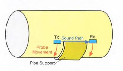
Rapid, medium range, ultrasonic screening technique for use on vessels, pipes and plates. Main application is the detection of corrosion in pipes under supports, but can be used for other restricted access situations (e.g. corrosion under nozzle reinforcement plates). The technique can detect corrosion emanating from inner and outer surfaces but cannot distinguish between the two conditions.
General inspection capabilities
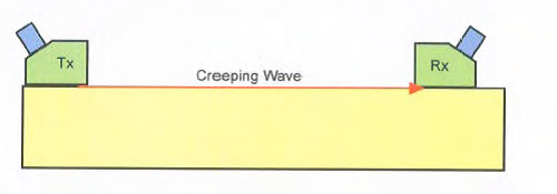
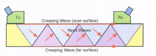
CHIME (Creeping / Head wave Inspection Method) provides total saturation of the material under inspection between two probes (one transmitter, one receiver, in pitch and catch formation). The CHIME probe shoes are angled to give shear waves at the critical angle, which results in 3 wave modes in the component:
- • Creeping waves – surface skimming compression waves:
2. Bulk waves – generally low amplitude due to mode conversion at surfaces:
3. critical angle (33°). A creeping wave is generated when the head wave interacts with the far surface. This repeats at both inner and outer surfaces.
Creeping waves generated at the near surface are detected by the receiver.
There is a direct relationship between the time interval between the peaks in the CHIME signals and the component thickness.
The complex system of wave modes produces a correspondingly complex signal pattern:
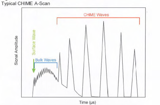
Changes in the amplitude and arrival time of received signals indicate the presence of a defect in the material. The A-scan signals are processed and usually imaged in shades of grey, dependent on signal amplitude (similar to TOFD data).
Although a screening technique, it is capable of semi-quantitative evaluation of defects. Signals can be categorised in three ways:
• <10% wall loss
• 10-40% wall loss
• >40% wall loss
Changes in transmission signal indicate the presence of a defect. Total signal loss indicates large defects and are easily detectable. The amount of signal loss is related to the area and depth (i.e. volume) of the defect – i.e. small volume defect = low signal
loss ; large volume = large signal loss.
The probe pair can be set up to give either circumferential (around pipe) or longitudinal beams (along pipe). For the former it is essential that the OD/ID ratio is
less than 1.19 or there will be gaps in coverage.
Operating Temperature
Normal ambient range for ultrasonic testing. Higher temperatures should be possible with appropriate transducers and equipment.
Inspection limitations
Suitable for pipes >75mm diameter for circumferential beams. For axial beams, there is no restriction on diameter.
For axial beams, the distance between the transmitting and receiving probes should be less than about 1m. For circumferential beams, the circumferential distance between probes should be less than about 700mm.
Suitable for thicknesses in the range 3 – 50mm.
Semi-quantitative only.
Only suitable for parallel or near-parallel walled material. Signals break up when wall thickness changes by 1mm over 75mm (13%).
Circumferential beam inspection limited by OD/ID ratio (must be less than 1.19).
Inspections can still be carried out on materials with a larger ratio but full volume coverage cannot be guaranteed.
There is no limit when probes are axially pointing.
The lateral extent of the area of wall loss, in the direction orthogonal to the ultrasound beam, needs to be comparable with or larger than the diameter of the CHIME probe
crystals (typically > 15mm), to give a significant loss in amplitude of the CHIME signals. Wall losses down to c. 10% of wall thickness can then be detected with high reliability, as demonstrated in the RACH, CRIS and GSP 236 trials.
Loss of CHIME signal amplitude can occur under a number of circumstances including:
• Cushion between pipe and support, which damps the creeping waves
• The presence of coatings
• Slight surface roughness on either the inspection surface or backwall.
• Loss of, or reduced coupling efficiency
The above mechanisms for loss of signal may limit the applicability of the technique, or if localised, could be mistaken for wall loss flaws (i.e. false calls). Experience to date indicates that the bulk waves signals are less sensitive to the above mechanisms than the CHIME peak signals.
Access requirements
Access required to manually attach scanner and probes. Adequate clearance required to manoeuvre scanning jig and probes around the pipe (approx 100mm overhead).
Surface condition requirements as for any UT inspection.