
Guided Ultrasonic Wave Technique (Wavemaker)
Guided Wave (UT) allows a large area of pipework to be inspected from a single transducer position.
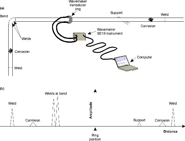
Wavemaker Schematic Diagram
- The Guided Wave (GW) travels along the length of the pipe and is reflected by changes in pipe stiffness (ncluding changes in acoustic impedance)
- A symmetrical change in wall thickness generates a uniformly reflected signal whereby a localised thickness change is recorded differently.
- A unit of piezoelectric transducers is clamped around the pipe and the GW
are sent simultaneously in both directions along the pipe with 100% screening coverage within its diagnostic length.
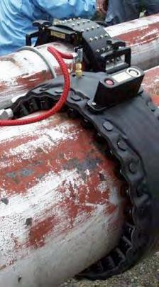
Wavemaker transducerring from GUL
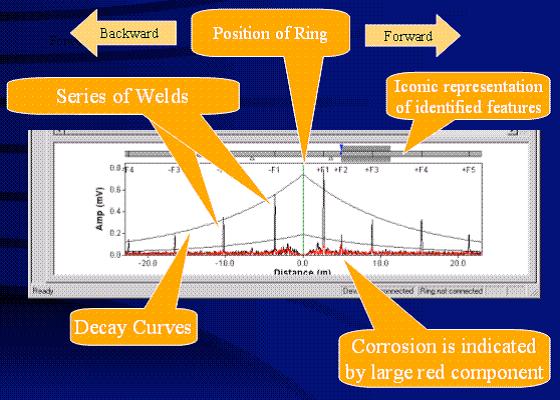
Example of results obtained using guided waves showing results obtained from both sides of the transducer ring
General inspection capabilities
- Rapid inspection of both internal and external defects on long pipe sections.
- Wavemaker technology is available both in screening and monitoring configuration (PIMS)
- Wavemaker technology is available both with external or internal access transduction system. T-scan (internal access system) is used to screen structures such as heat exchanger tubes.
- Wvemaker technology is also used for underwater inspection of risers and other pipelines
- Wavemaker G3 in screening configuration can detect metal loss and cracks >1% cross-sectional area depending on given conditions. From 5% cross sectional area most defects can according to the suppliers be detected with confidence.
- Wavemaker G3 in monitoring configuration can detect defects as small as 0.1% of the cross sectional area.
- Most suitable for inspection of long, un-flanged lengths of pipe.
- Guided waves are suitable for use on pipe diameters from 16mm (3/4″) -1800 mm (72”). Inflatable rings need to be used for bigger pipes.
- Wall thicknesses up to 75mm (3”) have been inspected.
- No couplant is required.
- Inspectable Materials include all metals
- Types of Pipe: Seamless, Longitudinally welded, Spiral welded
- Coatings: Polyurethane foam insulation, Mineral wool insulation, Epoxycoated, Tar epoxy coated, PVC coated, Painted.
- Other: Under ideal conditions roughly 100m can be inspected in a single test. The length of pipe that can be inspected is heavily dependant on several factors and range can be much lower than ideal case.
Inspection limitations
- Access to a surface is needed (360 degreed over 25cm axial length)
- The method cannot pass through flanges and does not inspect flanges.
- Standard practice is to only inspect past one bend at a time.
- High viscosity of the pipe content (for example bitumen) will attenuate the signal and can therefore be difficult to inspect.
- Pipes coated with attenuative coatings (e.g. soft thick and well adhered bitumen) can reduce range (or sensitivity). Coating condition and bond nature affect the ease.
Parameters affecting inspections capabilities
- The frequency of ultrasound will govern how small or big defect can be detected but higher frequency resulting in higher sensitivity will decrease the range.
- Type of coating utilised on pipe
- Viscosity of pipe content will affect inspectability
- Pipe geometries and condition.
- Internal deposits and lining