
Shearography Technique Datasheet
Basis of Technique
An optical method to detect surface strain variation induced by the presence of sub-surface defects.
General inspection capabilities
Shearography is a non-contact method for fast, large-area defect detection and structural analysis.
• Holographic and Speckle interferometry can produce surface maps of relative displacement
• Speckle techniques detect surface strain variation induced by the presence of the subsurface defect The instrument can identify composite structural defects such as delaminations, disbonds, impact damage, voids, inclusions and cracks. Detection is possible to depths up to 100mm in the material depending on structural rigidity and loading mechanisms.
Using the results gained from the instrument, engineers and designers can assess how an object is responding to an induced force. From this assessment they can then determine whether the component design needs changing or whether there are problems in the item as manufactured.
Basic Principle of Sheorography
Laser beams are monochromatic (single wavelength), highly directional and are spatially and temporally coherent. This coherent property of a laser beam, where all emitted waves are in phase with each other, enables its use for strain measurement. The beam incident on the target is reflected by its
surface. Most surfaces are not optically flat. The surface roughness causes the reflected waves of light to interfere with each other creating a grainy effect that is known as speckle.
The detection system comprises of an image shearing head, a phase stepper, an imaging lens and a camera. The strain field is produced by saving an image of the unstressed target, and subtracting all subsequent images from this reference image. As a mechanical or thermal stress is applied to the target surface, the phase of the speckle changes corresponding to the stress.
This is visible as fringes in the subtracted video.
Indications about defect location and appearance can be found by studying the resulting fringes.
Rigid movement produces displacement but no strain thus the technique is
insensitive to environmental disturbances and is well suited for industrial
applications.
Able to detect defects at depth within a variety of materials including
composites, honeycomb structures and thin plate.
Extensively used in aerospace / automotive industry. Other applications include:
Commercial applications that successfully utilise this technology include:
• Marine – currently used for new build, bi-annual and accident investigations by the RNLI
• Construction – validate design parameters and assess reinforcement bonding integrity
• Transport – within the rail industry to inspect bonding integrity and environmental effects
• Aerospace – determination of bonding strength in composite structures.
• Medical – prosthetic implant design evaluation and surgery investigations.
• Power Generation – gas turbine and wind turbine blade inspection System effective at
• Manufacture – defect free
• Repairs – verification
• In the field – transport/assembly damage
• Annual audits – defect propagation/RLP
• in situ testing
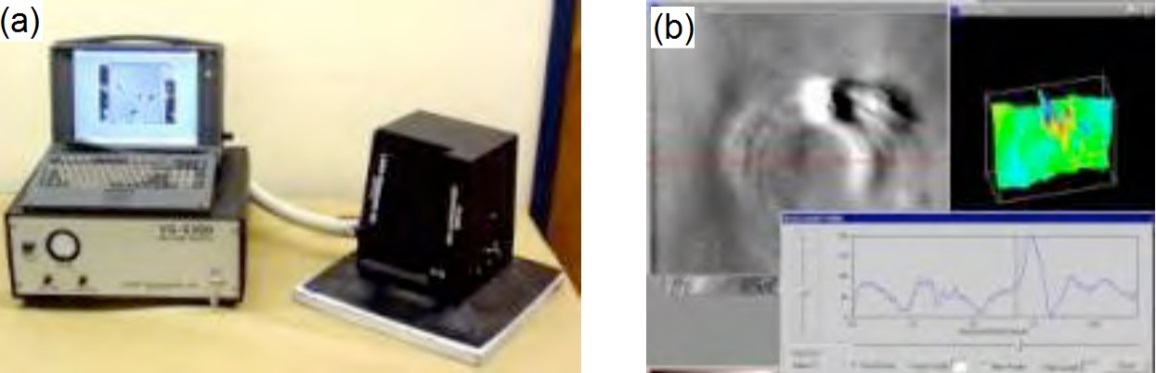
(a) Portable Shearography System. (b) Digital Shearography System
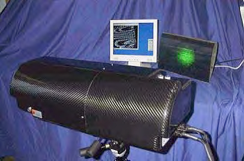
Laser Strain Mapper from Laser Optical Engineering
Inspection limitations
Vibration of surrounding structure? Can be viable if the system is mounted rigid to the structure under test such that both instrument and structure are vibrating in phase.
50mm deep defect canbe detected. Larger defects may be detected deeper into the structure.