
M-skip (Multi-Skip) Technique
Rapid medium range Ultrasonic Screening method for use on vessels, pipes and plates.
General inspection Capabilities
M-skip (Multi-Skip) uses two angled probes producing shear waves that propagate through the component between probes via multiple reflections from the front and back wall surfaces without mode conversion losses. Through the measurement and analysis of signal arrival times, quantitative information of the wall thickness and defect through-wall extent can be deduced.
Accurate measurements of average wall thickness along the line of sight between the probes can be obtained for approximately uniform thickness components. The technique can verify that there are no extended areas of significant wall loss under a pipe support or clamp. Changes in the received signal (arrival time and loss of amplitude) indicate the presence of a wall loss flaw in the material.
Wall loss flaws on either the inspection surface or the backwall can be detected. In some cases, the method can provide information on which surface contains the wall loss.
Primarily aimed at wall loss detection and sizing. Initial results suggest that the advantages and limitations are complimentary to those of CHIME
Provides rapid screening of pipework, particularly good for restricted access due to supports and similar obstructions (e.g. clamps). Can cover areas up to 1m probe-separation and various pipe diameters.
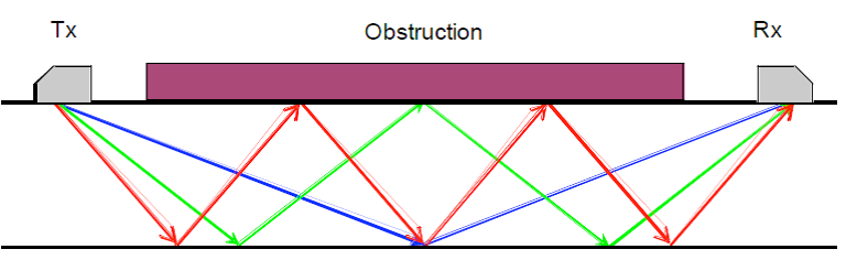
Concept of M-skip, showing the ray paths for the first three signals between thetransmitter (Tx) and the receiver (Rx), in the absence of any areas of wall loss.
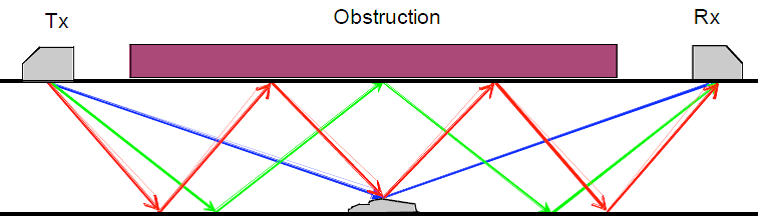
Concept of M-skip, showing the ray paths for the first three signals between the transmitter (Tx) and the receiver (Rx), in the presence of an area of wall loss
Inspection limitations
M-skip is a screening method which can indicate the presence of a defect/corrosion. There is evidence that quantitative information regarding through-wall extents of flaws, and the average wall thickness along the line of sight between the probes can be deduced.
Scans in a single direction do not provide information on the defect lateral extent in the direction along the line of sight between the probes. There can be uncertainties in the accuracy of the depths of wall loss measured by this technique, if the defect extent is unknown. In these cases the method does however provide an upper bound on the through-wall extent of the wall loss.
Upper bound limits are also likely to be obtained if two separate flaws are present in between probes in the same line of sight, although there is limited data on this case at present.
Transmitting and receiving probes must be within about 1m. Only suitable for parallel or near-parallel walled material, but these can include circumferential inspection of pipe walls.
Results should be augmented with a conventional UT inspection, if possible.
109 It is recommended that supplementary 0º wall thickness measurements are taken to establish the component wall thickness local to the M-skip probes within a scan, and also along the line of sight between the M-skip probes if access is available (e.g. at scan start and scan end positions for pipe support inspection).
Inspections can be carried out with M-skip probes pointing both axially and circumferentially. Lower angled probes are used when scanning circumferentially, to maintain an approximately constant incident angle on the ID surface.
The presence of coatings can significantly reduce the amplitude and quality of M-skip signals. The severity of this effect increases with the number of internal reflections experienced by the signals, and may depend on coating type.
For thin-walled components (less than about 10mm), isolated pitting flaws can give total loss of signal, and hence no information on flaw through-wall extent. Experience to data suggests that improved flaw sizing information is obtainable for wall thicknesses > 15mm. However, some very irregular, extended areas of wall loss can then also produce a total loss of signal, although this can be minimised by probe optimisation.
Access requirements
Access required to manually attach scanner and probes. Adequate clearance
required to manoeuvre scanning jig and probes around the pipe (approx 100mm overhead).
Probe separation must be less than 1m.
Surface condition requirements as for any UT inspection.
M-skip can be applied on curved pipe sections.