
TOFD Fast Screening Technique
The method uses regular TOFD equipment as used for inspection of welds.
Standard TOFD works well to detect far-side defects in the centre between the probes. To widen the footprint use is made of the mode-conversion waves as well. Shell Global Solutions has dedicated software to estimate the size of the footprint for a certain probe setup, as well as the detection threshold (i.e. a defect response detectable in front of the backwall response) and the sizing accuracy (i.e. the error occurring when the defect location has an offset within the footprint). Also software for automated batch-processing of TOFD scans to measure arrival times of lateral wave, compression and mode-conversion
signals from backwall and corrosion defects.

The footprint of TOFD Screening is made up of the compression backwall reflection and the modeconversion backwall reflection
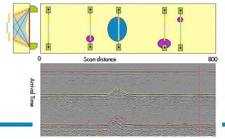
Example of detection of wall loss defects; there is uncertainty in the lateral position of the defect
General inspection capabilities
Applicable to components that can also be inspected with regular TOFD (in
relation to signal-to-noise characteristics and geometry). The Fast Screening capability is more effective for wall thicknesses above some 20-30 mm, and it can be applied to thicknesses of 100 mm and above.
The footprint varies dependent on the required detection sensitivity; This can be
typically:
30 mm wide footprint on a 20 mm WT; 80 mm footprint on a 100 mm WT.
The depth detection threshold will increase with wall thickness (i.e. probe frequency), from typically 0.5 mm on a 20 mm WT, to some 2 mm on a 100 mm WT.
The detection sensitivity can be around 5 mm diameter spherical hole in 20-100
mm WT.
The lateral wave provides a depth-reference of the near surface, which reduces thickness measurement errors related to paint layers.
The method is ideal for detection of small pitting in cladded vessels (of roll bond or explosion bond type; not welded overlay); There is a limitation in total wall thickness in view of the required detection threshold and depth sizing resolution within a 3 mm clad thickness.
Materials include low-alloy carbon steel and higher alloyed materials albeit with a possible reduction in sensitivity (plate material in equi-axed condition, not welded materials).
Inspection limitations
Method not so suited for thin wall materials (WT<15-20 mm) due to reduced footprint (reduced advantage over normal beam corrosion mapping systems) and due to lateral wave near surface resolution (WT<6 mm).
TOFD Screening is normally applied with any coating in place; this may give ringing of the lateral wave, which may hamper the detection of defect responses (and may limit the effectiveness of automated processing).
Inclusions in the material may be wrongly interpreted as corrosion pits, especially when they are located close to the backwall.
Access requirements
Dependent on probe deployment different quality access is required for the
operator:
-Manual scanning requires comfortable access to the surface for the scan operator.
– Mechanized scanning along a band requires access for applying the band and then putting the scanner on the band (so not necessarily full access is required to the scanned surface).
– Mechanized scanning with remotely operated magnetic-wheel scanner; this would require access from a platform to bring the scanner to the surface, after which it can access all locations on the vessel (out with its dead-zones).
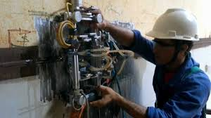
Operator scanning the TOFD-probes; note comfortable access to
vertical wall of the vessel, supporting scan-rate of 20 m2 per day.