
Alternating Current Fieled Measurement (ACFM) Method
Many structures and plant components require routine inspection to ensure their integrity. Conventional in-service methods such as Magnetic Particle Testing or Dye Penetrant require paint and coating removal and rely heavily on operator interpretation, at best these techniques can determine whether a defect exists but are unable to provide information on defect severity. In order to achieve this, the depth of the defect is required. This can then be used, together with Fracture Mechanics methods to determine whether the component is safe for continued operation.
The alternating current field measurement (ACFM) technique has been developed to provide reliable crack detection and depth sizing without the need to remove paint and coatings. In addition because there is no need for paint removal and repainting, the need for expensive scaffolding can often be avoided and instead the technique can be deployed using much more cost effective rope access methods.
ACFM is an electromagnetic inspection technique originally developed for subsea inspection in the offshore industry where there was a requirement to improve the reliability of in-service inspection and reduce the reliance on the inspector’s interpretation. The technique is now widely used across a range of infrastructure applications where quantitative measurements are made in order to determine structural integrity. The capabilities of the technique have been independently assessed leading to its acceptance by major international classification and certification Societies.
This paper will describe how the ACFM method works and how it differs from other electromagnetic methods. Examples of its application to a range of inspection tasks including bridges, cranes, pressure vessels, pipelines and transportation systems will be given, together with discussions on how automation of the process has virtually removed the requirement for skilled inspectors
Current flow around a defect
ACFM of Technique
The ACFM method is an electromagnetic inspection technique which can be used to detect and size surface breaking (or in some cases near surface) defects in both magnetic and non-magnetic materials. ACFM is a current perturbation technique and is fundamentally different to conventional eddy current techniques.
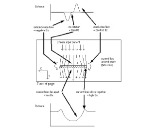
When an alternating current flows in a conductor it flows in a “skin” following the surface. If a surface breaking crack is present, this otherwise uniform sheet of current is disturbed. There is a magnetic field associated with this electrical field and the magnetic field disturbances (associated with the electrical current disturbances) can be measured using magnetic field sensors. Although the resulting magnetic field is complex, components can be chosen, which allow disturbances due to cracks to be identified and quantified.
Figure 1 shows schematically how the electrical field is disturbed on the surface by the presence of a crack. In practice, two components of the magnetic field are measured, Bx along the length of the defect, which responds to changes in surface current density and gives an indication of crack depth and Bz, which gives a negative and positive response at either end of the defect, caused by current generated poles, and thus gives an indication of length.
In standard applications two field sensors are used and these are incorporated into a probe head which also introduces the uniform current into the component using a field inducer. The probe does not require any special scanning patterns. In order to inspect for weld toe cracks, the probe is simply moved along the weld toe.
Since the signals produced in the sensors were extremely small, TSC developed an instrument, the Crack Microgauge, which controls the inducing field and amplifies and digitises the sensor readings. All functions are under the control of an onboard microprocessor, which sends data to a standard laptop PC.
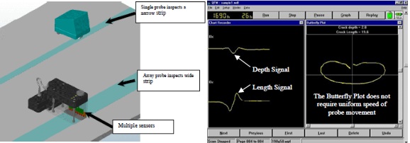
Specialist Windows software is used to control the inspection and display and store the results. Figure 2 shows a typical ACFM data display produced when the probe is scanned over a defect. In the left hand side of the screen, the Bx and Bz readings are plotted. A defect is indicated by a trough in the Bx plot, the deepest point coinciding with the deepest part of the crack, associated with a peak and trough in the Bz plot, which indicates the location of the crack ends. To aid in interpretation, the Bx and Bz readings are plotted against each other on the right hand side of the screen where a characteristic loop is formed in the presence of a defect. This display, called the “butterfly plot”, is unique to ACFM and, because it is insensitive to probe speed, greatly enhances interpretation.
Once a defect is identified the depth can be determined by entering the length of the defect, found by marking the locations of the Bz peak and trough on the sample, and choosing two points from the Bx trace. The software algorithms instantly return a value for crack length and depth, which is displayed above the defect indication on the screen.
Because the ACFM method is actually measuring magnetic fields, it requires no electrical contact with the surface and so does not require paint coatings to be removed before inspection. Non-conducting cotings up to 5mm thick can be accommodated with standard probes. In order to determine the size of the defect, a measure of the size of disturbances of the field is made. This is then fed into mathematical models, developed at University College London which are based on theoretical prediction of current flow around cracks. These theoretical models have been shown to correlate well with the physical measurement of magnetic fields made with ACFM equipment [1,2].
The ACFM method works both above and below water. The use of a uniform field removes many of the problems associated with conventional electromagnetic (eddy current) techniques. These rely heavily on operator skill, in particular when used around welds and geometric changes.
Of particular benefit is the fact that the ACFM system is very insensitive to probe manipulation. The butterfly plot (Figure 2) removes the time base from the data presentation which means that if a defect is scanned slowly, quickly or even in a series of finite steps, the butterfly presentation will still be displayed. This means that it is possible for a second person to move the probe whilst the data is viewed by the “expert”. This immediately offers a very significant benefit because it means that the person moving the probe does not need to be a specialist inspector. This benefit is used to good effect for subsea inspection where the diver does not need to be a trained inspector, the inspector remains above water controlling the inspections and analysing the data. It now forms the basis for a number of inspection applications above water.
Current flow around a defect
TyPical Appliations
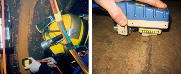
Because the technique can be used as part of a two man team, it is routinely used in conjunction with industrial rope access (abseiling). The principle is the same as for diving, the climber delivers the probe while the inspector remains in a “standard” working environment. Figures 4 shows a rope access technician deploying ACFM on a painted crane structure
ACFM Inspection